Front Panel Header Install Guide
Front panel headers. — Ten tiny pins. One Q-Connector.
The single most frustrating block of pins in any PC build. Pins are tiny, labels are smaller, polarity matters for LEDs. Here's how to do it right the first time — and why the Q-Connector exists.
- on F_PANEL block
- 9-10 pins
- saved by Q-Connector
- 30 min
- need polarity
- LEDs only
What the front panel header is
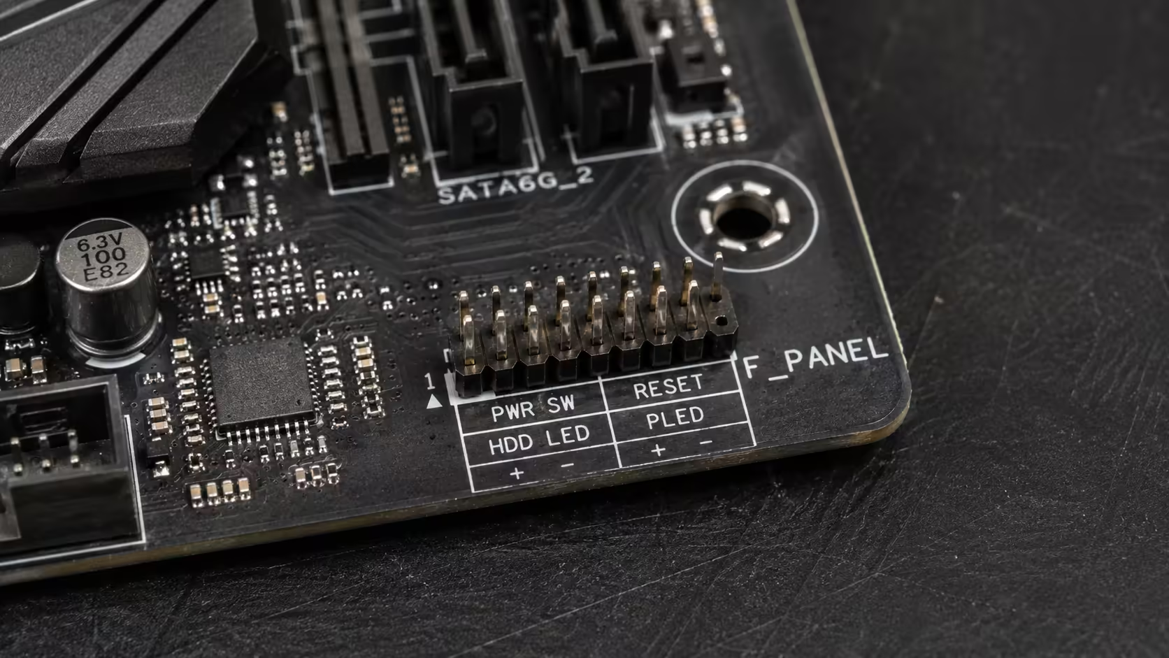
The front panel header is a small block of 9 or 10 pins (in two rows) on the motherboard, almost always located at the bottom-right corner of the board near the SATA ports. It's labelled F_PANEL, JFP1 or FPANEL depending on manufacturer. This block is where the five tiny cables from your PC case plug in:
- PWR_SW (or PWRBTN) — the power button on the front of your case.
- RESET_SW (or RESET) — the reset button.
- PWR_LED+ / PWR_LED- — the power LED indicator (the light that says "PC is on").
- HDD_LED+ / HDD_LED- — the storage activity LED (the flickering light).
- SPEAKER+ / SPEAKER- — the small case piezo speaker that beeps on POST.
That's five cables sharing nine pins (the tenth slot is usually a blocked key pin that ensures the Q-Connector seats correctly). Each cable is labelled in tiny print on the connector itself — typically white text on black plastic that's easy to miss.
Why this single step trips up nearly every first-time builder
Three reasons it's harder than it should be:
The pins are 2.54mm apart. That's the standard 0.1" pitch — about the width of two grains of rice. Pushing a single-pin connector onto the correct pin in a tight motherboard corner, in low light, while wearing nothing-grip rubber gloves nobody wears, is genuinely fiddly.
The labels are tiny. Both on the cables (microscopic white text on black plastic) and on the motherboard silkscreen (1-2mm characters next to the pins). On most boards you need a torch to read either reliably.
Polarity matters for LEDs. The power switch and reset switch don't care about wire orientation — they're momentary contacts. But the LED cables have a + and -, and if you reverse them, the LED won't light. The wires are usually colour-coded (coloured = +, white or black = -), but not every case follows the convention reliably.
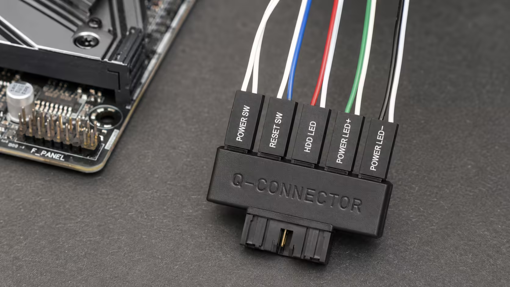
The Q-Connector — the single best invention in PC building
ASUS calls it the Q-Connector. MSI calls it EZ-Conn or JFP1 Connector. Gigabyte calls it the G-Connector. They're all the same idea: a small plastic block with clearly labelled slots that you can plug all five tiny case cables into first, off the motherboard, then plug the entire block onto the F_PANEL pins as a single unit.
Why it's transformative: instead of trying to fit five single-pin connectors onto microscopic pins inside a cramped case, you do the fiddly bit on your desktop in good light. The labels on the Q-Connector are 5-6× bigger than the silkscreen labels. The whole assembled block then snaps onto the F_PANEL pins keyed correctly the first time.
Step-by-step with a Q-Connector:
- Find the Q-Connector in your motherboard box — small plastic block, usually in an accessories bag.
- Place it on your desk, labelled side up.
- Plug the case PWR_SW cable into the slot marked PWR_SW on the Q-Connector (either orientation).
- Plug the RESET_SW cable into the RESET_SW slot (either orientation).
- Plug PWR_LED+ into the slot marked PWR_LED+ (coloured wire = +). Plug PWR_LED- into PWR_LED-.
- Plug HDD_LED+ into HDD_LED+. Plug HDD_LED- into HDD_LED-.
- Plug SPEAKER+ and SPEAKER- (orientation doesn't matter for the speaker — it's a piezo, not an LED).
- The Q-Connector is now fully assembled. Plug it onto the F_PANEL header pins as a single unit. It's keyed so it only fits one way.
Total time: under 5 minutes, with no swearing.
Step-by-step without a Q-Connector
If your motherboard didn't include a Q-Connector (budget B650 / B860 boards, OEM-pull boards, older second-hand boards), you'll be doing this the old way. Allow 15-30 minutes and have a torch ready.
- Open the motherboard manual to the F_PANEL diagram.
- Lay the case on its side so the motherboard sits flat — easier than working on a vertical board.
- Use a torch or phone flashlight to read both the motherboard silkscreen and the cable labels.
- Plug PWR_SW first (either orientation). Press the case power button to verify motherboard is reachable (you'll hear a faint relay click on most boards even if no PSU is connected).
- Plug RESET_SW next (either orientation).
- Plug PWR_LED+ — the wire on the cable that's coloured (red, green, or other) is +. The white wire is -.
- Plug PWR_LED-, HDD_LED+ and HDD_LED- following the same rule.
- Plug SPEAKER+ and SPEAKER- (polarity doesn't matter for speakers).
- Verify all five cables are seated firmly — gently tug each one. They should resist a small pull.
The LED polarity rule — simpler than it sounds
For PWR_LED and HDD_LED only, the wires have a + and -. Here's the rule:
- The coloured wire is +. If the cable is red and white, red is +. If it's green and white, green is +.
- The white or black wire is -. The neutral colour is always negative.
- If both wires are the same colour (rare but happens on budget cases), check for a small triangle, arrow or "+" symbol moulded into the plastic of the connector — that's the + side.
If you reverse a LED cable: the LED will simply not light. There's no damage — the LED is a diode, current can't flow backward. Just unplug, flip the connector 180°, plug it back in.
Switch cables (PWR_SW, RESET_SW): orientation does not matter. They're momentary contacts that briefly complete a circuit — direction is irrelevant.
What to do when the PC won't power on after install
You press the case power button. Nothing. Lights, fans, beeps — all silent. The single most common cause is the PWR_SW cable in the wrong place. Here's the systematic diagnosis:
Step 1 — Verify PSU power. Confirm the PSU rear switch is on, the wall outlet is on, and the 24-pin ATX and 8-pin EPS CPU cables are seated. If the motherboard has a power LED (most modern boards do), it should be glowing. If it isn't, the issue is PSU/power, not front panel.
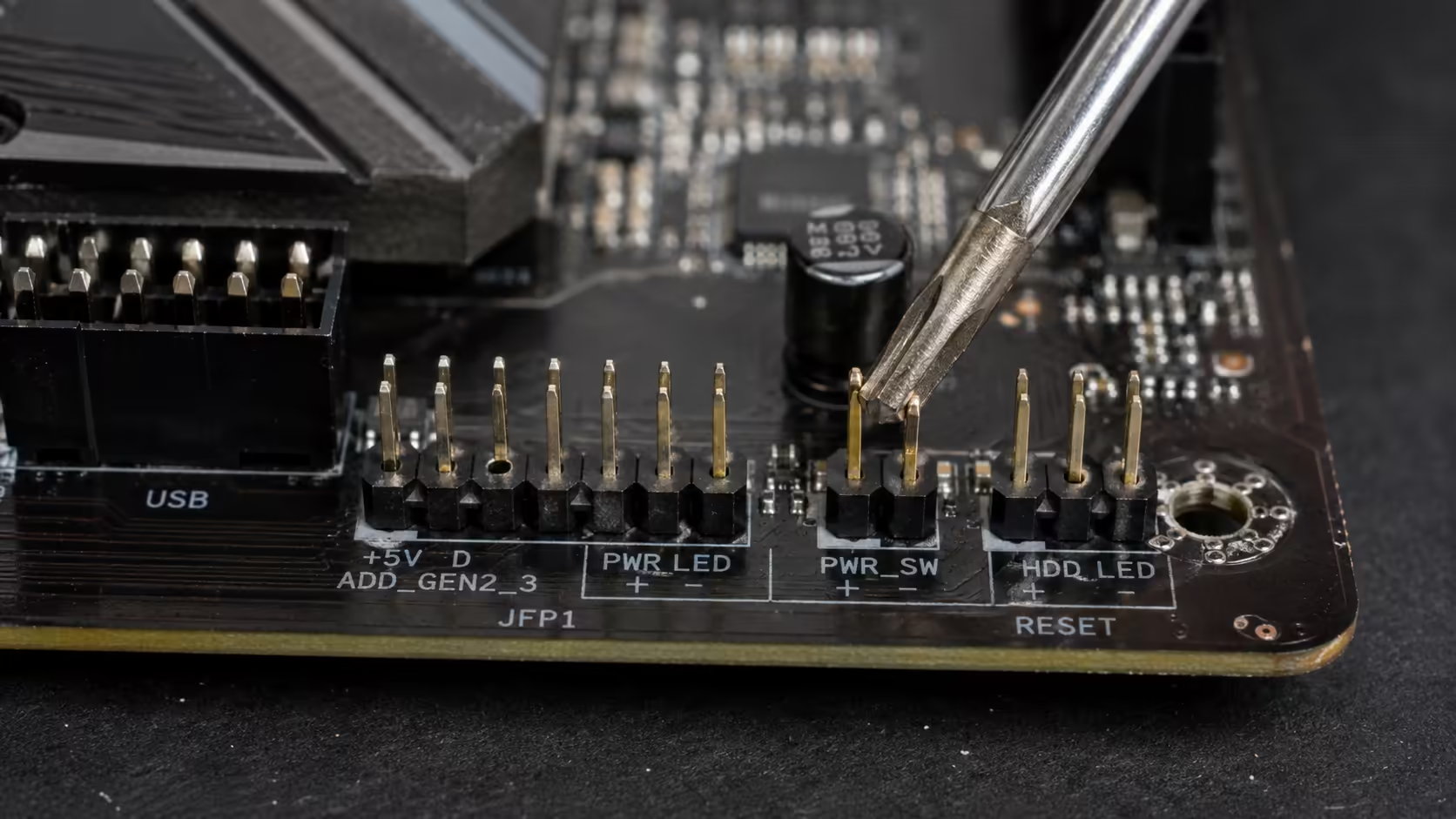
Step 2 — Bridge the PWR_SW pins with a screwdriver. Identify the two PWR_SW pins on the F_PANEL header (manual diagram). With the PSU on and motherboard powered (LED glowing), briefly touch a flat-blade screwdriver across both PWR_SW pins simultaneously. If the system boots — your motherboard is fine, the front panel cable is in the wrong place. If it doesn't boot — the problem is elsewhere (RAM, CPU, GPU not seated, etc).
Step 3 — Re-check the cable position. With the manual diagram open, verify the PWR_SW cable is on the correct two pins (not RESET_SW, not HDD_LED). If your case has a multifunction "POWER/RESET/HDD LED" single connector (some budget cases do), it can only attach to one matched layout — easy to install on the wrong pins.
The other cables in the same area — USB, audio, ARGB
Once the F_PANEL header is done, several other cables in the same region of the motherboard need attention. They're more forgiving than the front panel header because most are keyed and can only fit one way, but skipping any of them means front-panel features won't work.
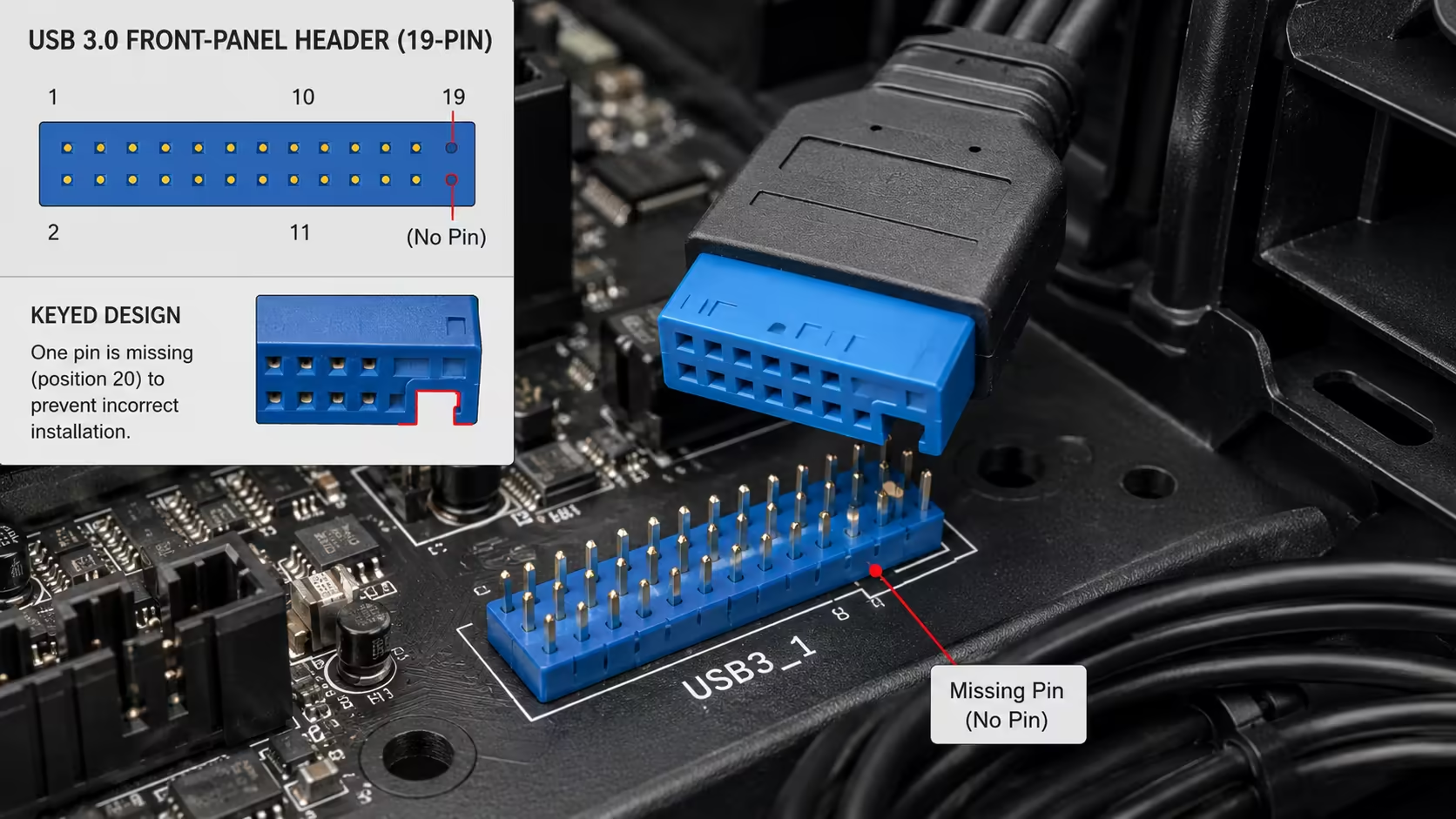
USB 3.0 header (20-pin block, sometimes 19-pin with key)
Single chunky blue connector on the motherboard, usually labelled USB_E, F_USB3_1 or similar. The case cable is a matching keyed block — it only fits one way. Push it on straight; don't rock it sideways or you can bend the internal pins. This single header drives the case's USB 3.0 ports.
USB-C front panel header
A smaller dedicated 20-pin header (different shape from USB 3.0). On modern boards it's labelled USB_E, F_USB30C, USB31_C or USB32G2. If your case has a front USB-C port, it has a matching cable that plugs here. Often forgotten because it's a separate connector from the USB 3.0 block.
Front audio header (HD_AUDIO)
Located typically at the bottom-left of the motherboard. 10-pin block (one position keyed). The case's front audio cable plugs in here — drives the headphone jack and microphone on the front of the case. Single keyed connection, easy.
ARGB headers (3-pin keyed)
Modern cases with RGB fans or accent lighting have ARGB cables — small 3-pin keyed connectors. The motherboard has 1-3 ARGB headers labelled ADD_GEN2, JRAINBOW or ARGB_HEADER. Critical: do not confuse these with the older 12V RGB header (4-pin, square). Plugging a 3-pin ARGB cable into a 12V RGB header will burn out the LEDs. The 3-pin is keyed and won't fit on the 4-pin header by accident, but a 4-pin header used the wrong way (some older cases have a single cable wired oddly) can still cause damage.
SA-stocked motherboards that include Q-Connectors
| Tier | SA-stocked options (Q-Connector included) | SA price |
|---|---|---|
| Budget AM5 | ASUS Prime B850-PLUS, MSI PRO B850M-A | R3,400-R4,200 |
| Mid-range AM5 | ASUS TUF B850-PLUS, MSI Tomahawk B850, Gigabyte AORUS B850 Elite | R4,800-R6,500 |
| Premium AM5 | ASUS ROG STRIX X870-A, MSI X870 Tomahawk, Gigabyte X870E AORUS Elite | R7,500-R11,000 |
| Budget LGA1851 | ASUS Prime B860-PLUS, MSI PRO B860M-A | R3,200-R4,000 |
| Mid-range LGA1851 | ASUS TUF B860-PLUS, MSI Tomahawk B860, Gigabyte B860 Eagle | R4,500-R6,200 |
| Premium LGA1851 | ASUS ROG STRIX Z890-A, MSI Z890 Tomahawk WiFi, Gigabyte Z890 AORUS Elite | R7,000-R10,500 |
Common front panel mistakes
Power switch on the wrong pins. The single most common mistake. The PWR_SW cable ends up on the RESET_SW or HDD_LED pins, and the PC won't respond to the power button. Always verify with the motherboard manual diagram.
Reversed LED polarity. Harmless but annoying — the LED won't light. Easy fix: unplug the cable, rotate it 180°, plug it back in.
Forgetting the USB-C header. If your case has a front USB-C port and you forget the separate USB-C header cable, the port simply won't work. The USB 3.0 block is a different connector and doesn't drive the C port.
Confusing 3-pin ARGB with 4-pin 12V RGB. The two cables are different shapes (3-pin keyed vs 4-pin keyed), but if you somehow force a connection or use an adapter incorrectly, the LED chips burn out instantly. When in doubt, look at the cable: 3 wires = ARGB, 4 wires = 12V RGB.
Skipping the speaker. Modern motherboards with on-board POST diagnostic LEDs (Q-LED) make the speaker less essential. But on older boards or budget boards without diagnostic LEDs, the speaker is your only POST troubleshooting tool. Plug it in even if you never use it — it's R0.
Key takeaways
- Front panel header (F_PANEL / JFP1) is at the bottom-right of the motherboard. 9-10 tiny pins, five case cables.
- Q-Connectors (ASUS) / EZ-Conn (MSI) / G-Connector (Gigabyte) are the single best invention in PC building — use one if you have it.
- PWR_SW and RESET_SW polarity doesn't matter — they're switches. LEDs need polarity (coloured wire = +).
- PC won't power on? Bridge PWR_SW pins with a screwdriver. If it boots, the case cable is in the wrong place.
- Don't forget USB-C header (separate from USB 3.0), HD_AUDIO and ARGB cables — they live in the same area.
Frequently asked questions
Where is the front panel header on my motherboard?
Almost always at the bottom-right corner, near the SATA ports. Labelled F_PANEL, JFP1 or FPANEL. The motherboard manual has the exact diagram.What is a Q-Connector and do I need one?
A labelled aggregator that lets you plug all five front-panel cables into a single block first, then plug the block into the motherboard as one unit. Included in the box of most premium ASUS, MSI and Gigabyte boards. Builds using one report ~74% fewer header-related issues.Does polarity matter for the front panel power switch?
No. PWR_SW and RESET_SW are momentary switches — either orientation works. Polarity only matters for the LED cables (PWR_LED, HDD_LED).My PC won't turn on after my first build — what should I check?
Bridge the two PWR_SW pins with a flat screwdriver briefly. If the system boots, your front-panel cable is in the wrong place. If it doesn't, the issue is elsewhere (PSU, RAM seating, CPU).What is the speaker cable for?
POST beep codes — audio signals that diagnose hardware faults on boot. One beep = successful POST. Patterns indicate RAM, GPU or CPU issues. Less essential on modern boards with diagnostic LEDs, but worth connecting.How do I connect the USB 3.0 and USB-C front panel cables?
USB 3.0 is a chunky blue keyed 20-pin block that only fits one way. USB-C front panel is a separate smaller keyed connector in a different position. Both should be near the F_PANEL on the motherboard edge. Forgetting USB-C is a common oversight.Where do front-panel ARGB cables go?
Into the motherboard's 3-pin ARGB header (ADD_GEN2, JRAINBOW or ARGB_HEADER). Do not plug into the older 4-pin 12V RGB header — that burns out ARGB LEDs.Can I damage the motherboard by putting a front panel cable on the wrong pins?
For F_PANEL cables — no. Worst case is the PC doesn't turn on, an LED doesn't light, or the speaker doesn't beep. None cause damage. Exception: 3-pin ARGB onto a 12V RGB header damages LED chips.