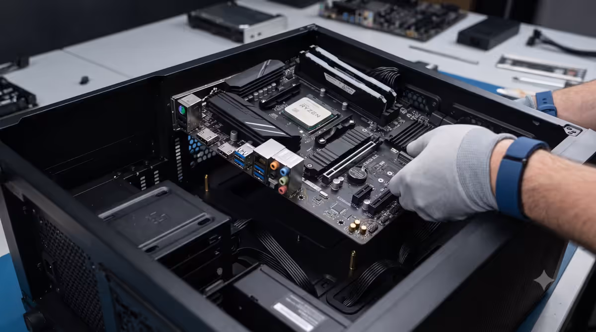
Install How-To · Motherboard
How to install a motherboard. — I/O shield first. Standoffs verified. Star pattern.
The single step where a missed standoff or cross-threaded screw can damage the most expensive part of your build. Three checks before the board touches metal eliminate every risk.
- install sequence
- 5 steps
- screws · ATX
- 6-9
- first time
- 10 min
Before you start
A few setup steps that save time and prevent damage. Your motherboard should already have:
- CPU installed and retention arm closed. See our CPU install guide if you haven't done this.
- RAM seated in both DIMM slots with both clips locked. Use slots A2 and B2 (2nd and 4th from CPU) for dual-channel.
- M.2 SSDs installed in their slots. 30° insertion angle, then screw down.
- CPU cooler NOT installed yet (for air towers — too big to install before mounting). For AIOs, install the pump block now, run radiator into case during step 4.
Tools you need: Phillips #2 (PH2) magnetic screwdriver, ideally with a 10-15cm shaft. Optional: small torch for inspecting standoff positions, anti-static wristband (if available; not essential for most builders).
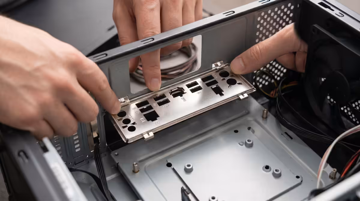
The I/O shield — install it first, always
The I/O shield is the metal plate that surrounds the rear ports (USB, ethernet, audio). It does two jobs: blocks dust and EMI from entering through the rear gap, and provides labels for the ports.
Two scenarios in 2026:
- Pre-attached. Most modern motherboards from B650 / B760 and higher come with the I/O shield permanently attached to the motherboard itself. Skip this step entirely — the shield mounts with the board.
- Separate. Budget motherboards and older models ship the shield in a separate plastic sleeve. Install it in the case BEFORE the motherboard. Press it into the rear opening from the inside until all four corners click into place. Some shields require firm pressure — make sure you've oriented it correctly (port labels visible from outside the case).
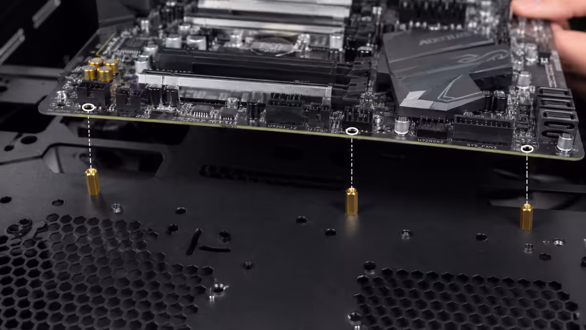
Standoff verification — the rule that prevents disaster
Standoffs are the small brass or steel spacers that raise the motherboard above the case tray. They serve two functions: (1) prevent the back of the PCB from shorting against the metal case, and (2) provide screw threading for motherboard mounting.
The rule: count the motherboard's screw holes. Verify EXACTLY that many standoffs are installed in the case, in matching positions. No more, no less.
| Motherboard size | Standoff count | Typical positions |
|---|---|---|
| ATX (305 × 244mm) | 9 standoffs | 3×3 grid |
| mATX (244 × 244mm) | 6-8 standoffs | Reduced grid |
| ITX (170 × 170mm) | 4 standoffs | 4 corners |
| E-ATX (305 × 330mm) | 9-12 standoffs | Extended grid |
Most modern cases come with standoffs pre-installed in the ATX positions. If you're using a smaller motherboard, you'll need to remove extra standoffs that don't match your board's screw holes — a 5mm or 6mm hex socket (often included in cases) removes them cleanly.
The 5 install steps
- 1
Install the I/O shield in the case
If not pre-attached. Press from inside the case into the rear opening until all four corners click. Orientation: port labels visible from outside. - 2
Count standoffs vs motherboard screw holes
Hold the motherboard above the case (don't lower yet). Every screw hole on the board should align with a standoff. Remove any extras, add any missing. - 3
Lower the motherboard at a slight tilt
Tilt the board so the rear ports clear the I/O shield first — the shield's metal tabs would otherwise catch on the port edges. Once the rear ports are positioned through the shield, lower the rest of the board flat onto the standoffs. - 4
Start every screw by hand first
Place a screw at the top-left corner. Turn it by hand (no screwdriver yet) until it threads cleanly. Repeat for all other screw positions. This prevents cross-threading — once a screw is started straight, the driver can't go wrong. - 5
Tighten in a star pattern
Use the screwdriver to tighten screws in alternating opposite-corner order: top-left, then bottom-right, then top-right, then bottom-left, then centre, etc. Keep tension even across the board. Stop each screw the moment resistance increases sharply. The board should feel firmly mounted but not stressed.
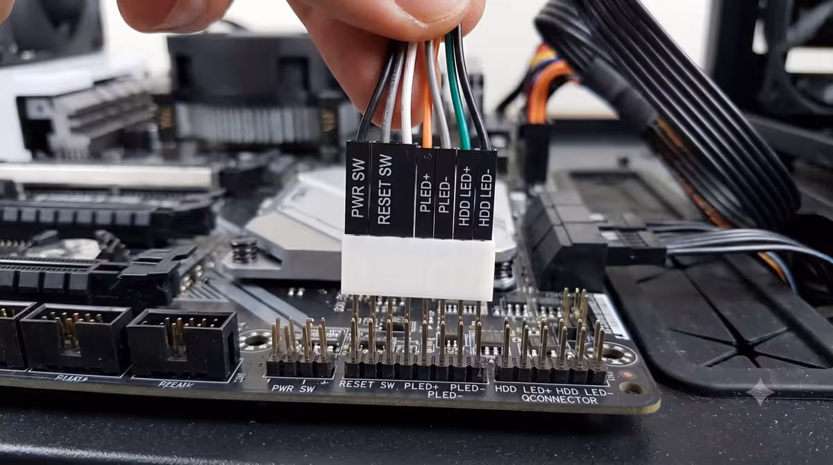
Connect the front panel headers (right after mounting)
The trickiest single connection on a build. The front-panel header is a 9-10 pin connector typically at the bottom-right of the motherboard, labelled F_PANEL, JFP1, or similar. Five tiny cables from the case plug here:
- Power switch (POWER SW) — turns the PC on/off. Polarity doesn't matter.
- Reset switch (RESET SW) — reset button. Polarity doesn't matter.
- Power LED (PLED +/-) — the on/off light. Polarity matters; LED won't light if reversed.
- HDD LED (HDD LED +/-) — disk activity light. Polarity matters.
- Speaker (SPEAKER) — POST beep speaker. Some cases skip this; polarity doesn't matter.
The shortcut: many ASUS, MSI and Gigabyte motherboards include a "Q-Connector" adapter in the box — a small block that aggregates all front-panel pins into a single labelled connector. Plug the case's cables into the Q-Connector first, then plug the Q-Connector into the motherboard as one unit. Makes the whole process trivial.
Without a Q-Connector: open the motherboard manual to the front-panel header diagram. Match each cable label to the pin label. Use thin tweezers or careful fingers — the connectors are tiny.
Common motherboard install mistakes
Forgetting the I/O shield. The cliché mistake. Verify before lowering the board.
Extra standoff causing a short. The dangerous mistake. Always verify standoff count vs board screw holes.
Over-tightening screws. Cracks PCB traces or strips standoff threads. Tighten until resistance just increases, then stop.
Cross-threading. Forcing a screw at an angle instead of straight. Back the screw out completely and restart from above.
Forgetting to plug in CPU 8-pin power. Cable goes at the TOP of the motherboard, separate from the 24-pin. Hardest to forget if you do it right after the motherboard is mounted.
What's next — after the motherboard is mounted
- Connect the 24-pin main power cable on the right side of the motherboard.
- Connect the 8-pin CPU power cable at the top, above the CPU socket. Don't skip this — most common "PC won't boot" cause.
- Install the CPU cooler. Air tower goes in now; AIO radiator + fans mount to case.
- Connect the front panel headers. Use Q-Connector if your board includes one.
- Install the GPU into the top PCIe x16 slot. Plug in PCIe power cables from PSU.
- Connect SATA cables and case fans. Tidy cable management.
- First boot. Enter BIOS, enable XMP/EXPO, verify temps. Then install Windows.
Key takeaways
- I/O shield first. Standoffs verified second. Motherboard last. Skip the order and you'll redo work.
- Standoff count must match screw-hole count exactly. Extras cause shorts, missing cause flex damage.
- Start every screw by hand before using the driver. Prevents cross-threading.
- Star tightening pattern keeps tension even. Stop the moment resistance increases sharply.
- Q-Connector adapters (when included) turn front-panel cables from frustrating into trivial.
Frequently asked questions
Do I install the I/O shield before or after the motherboard?
Before. The shield goes into the case opening first. If your motherboard has it pre-attached, no separate install needed.What happens if I skip a motherboard standoff?
Missing causes PCB flex damage. Extra (under non-screw-hole position) causes shorts that destroy the board on first power.How tight should motherboard screws be?
Snug, never torqued. Stop when resistance just starts to increase. Over-tightening cracks PCB traces.What screwdriver do I need to install a motherboard?
Phillips #2 magnetic with 10-15cm shaft. R80-R150 at any SA hardware store.In what order do I tighten motherboard screws?
Hand-start all first. Then star pattern: alternating opposite corners outward. Keeps tension even.How do I connect the front panel cables?
Use the Q-Connector adapter if your motherboard includes one. Otherwise refer to manual's F_PANEL pin layout. LEDs are polarity-sensitive; switches are not.Should I install M.2 SSDs before or after mounting the motherboard?
Before — much easier with board flat on its box than vertical in case. Same for CPU and RAM.How long should motherboard installation take?
15-25 min for first-timers. 5-10 min for experienced builders. Don't rush standoff verification or front-panel routing.